PCB Trace Parameters
Single-Ended (Z0)
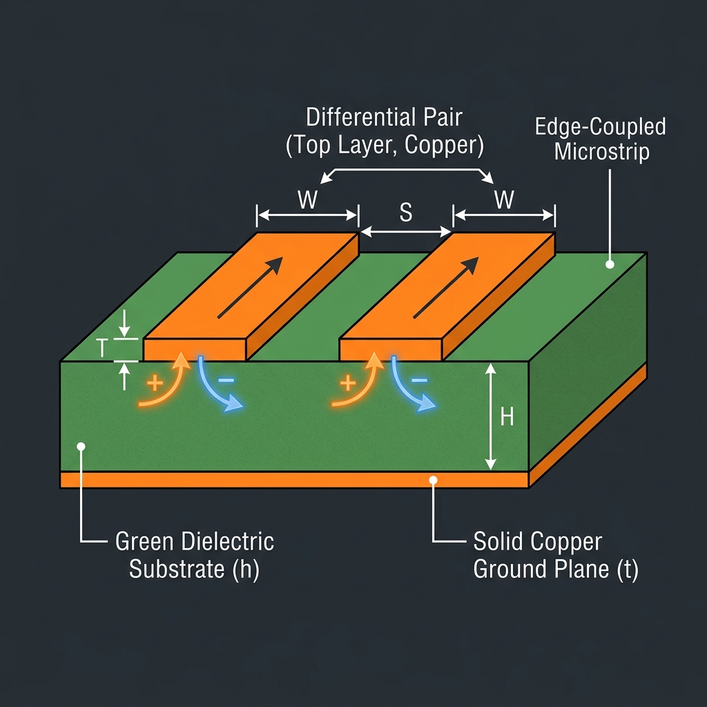
Differential (Zdiff)
Calculated using IPC-2141A edge-coupled microstrip approximations.
Understanding Differential Pair Impedance
In high-speed digital design (such as USB, PCIe, HDMI, and LVDS for FPGAs), signals are transmitted differentially to reduce electromagnetic interference (EMI) and improve signal integrity. A differential pair consists of two tightly coupled traces.
Because the traces are coupled, the differential impedance (Zdiff) is not simply twice the single-ended impedance (Z0). The electric fields between the traces interact, effectively lowering the total impedance. The closer the traces are to each other (smaller S), the stronger the coupling, and the lower the differential impedance.
This calculator uses the standard IPC-2141A approximations for edge-coupled surface microstrips. Note that for highly critical multi-gigabit signals, a 2D field solver is recommended for exact impedance matching.